- 您现在的位置:买卖IC网 > Sheet目录3884 > PIC16F628T-04E/SO (Microchip Technology)IC MCU FLASH 2KX14 18-SOIC
2009 Microchip Technology Inc.
DS40044G-page 105
PIC16F627A/628A/648A
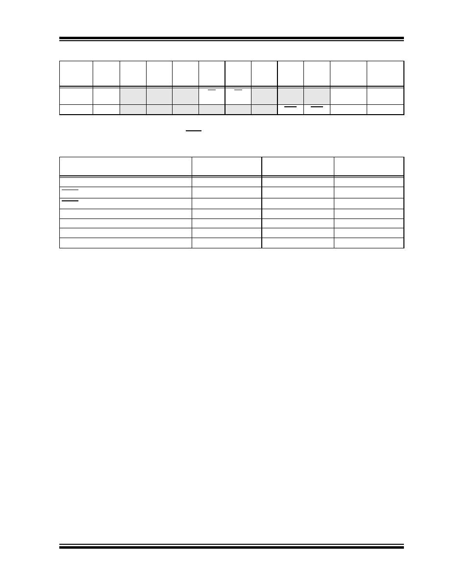
TABLE 14-5:
SUMMARY OF REGISTERS ASSOCIATED WITH BROWN-OUT RESET
TABLE 14-6:
INITIALIZATION CONDITION FOR SPECIAL REGISTERS
Address
Name
Bit 7
Bit 6
Bit 5
Bit 4
Bit 3
Bit 2
Bit 1
Bit 0
Value on
POR Reset
Value on all
other
Resets(1)
03h, 83h,
103h, 183h
STATUS
IRP
RP1
RPO
TO
PD
Z
DC
C
0001 1xxx
000q quuu
8Eh
PCON
—
OSCF
—POR
BOR
---- 1-0x
---- u-uq
Legend:
x
= unknown, u = unchanged, - = unimplemented read as ‘0’, q = value depends upon condition.
Shaded cells are not used by Brown-out Reset.
Note
1:
Other (non Power-up) Resets include MCLR Reset, Brown-out Reset and Watchdog Timer Reset during normal operation.
Condition
Program
Counter
Status
Register
PCON
Register
Power-on Reset
000h
0001 1xxx
---- 1-0x
MCLR Reset during normal operation
000h
000u uuuu
---- 1-uu
MCLR Reset during Sleep
000h
0001 0uuu
---- 1-uu
WDT Reset
000h
0000 uuuu
---- 1-uu
WDT Wake-up
PC + 1
uuu0 0uuu
---- u-uu
Brown-out Reset
000h
000x xuuu
---- 1-u0
Interrupt Wake-up from Sleep
PC + 1(1)
uuu1 0uuu
---- u-uu
Legend:
u
= unchanged, x = unknown, - = unimplemented bit, reads as ‘0’.
Note
1:
When the wake-up is due to an interrupt and global enable bit, GIE is set, the PC is loaded with the interrupt vector
(0004h) after execution of PC + 1.
发布紧急采购,3分钟左右您将得到回复。
相关PDF资料
PIC18F448T-I/L
IC MCU FLASH 8KX16 W/CAN 44-PLCC
PIC18LF448T-I/L
IC MCU FLASH 8KX16 LV CAN 44PLCC
PIC18LF458T-I/L
IC MCU FLSH 16KX16 LV CAN 44PLCC
PIC16F627-04E/P
IC MCU FLASH 1KX14 18-DIP
PIC16F627-20E/P
IC MCU FLASH 1KX14 18-DIP
PIC16C54C-20I/P
IC MCU OTP 512X12 18DIP
PIC16F627T-04E/SO
IC MCU FLASH 1KX14 18-SOIC
PIC18LF448-I/L
IC PIC MCU FLASH 8KX16 44PLCC
相关代理商/技术参数
PIC16F628T-04E/SS
功能描述:8位微控制器 -MCU 3.5KB 224 RAM 16 I/O RoHS:否 制造商:Silicon Labs 核心:8051 处理器系列:C8051F39x 数据总线宽度:8 bit 最大时钟频率:50 MHz 程序存储器大小:16 KB 数据 RAM 大小:1 KB 片上 ADC:Yes 工作电源电压:1.8 V to 3.6 V 工作温度范围:- 40 C to + 105 C 封装 / 箱体:QFN-20 安装风格:SMD/SMT
PIC16F628T-04I/SO
功能描述:8位微控制器 -MCU 3.5KB 224 RAM 16 I/O RoHS:否 制造商:Silicon Labs 核心:8051 处理器系列:C8051F39x 数据总线宽度:8 bit 最大时钟频率:50 MHz 程序存储器大小:16 KB 数据 RAM 大小:1 KB 片上 ADC:Yes 工作电源电压:1.8 V to 3.6 V 工作温度范围:- 40 C to + 105 C 封装 / 箱体:QFN-20 安装风格:SMD/SMT
PIC16F628T-04I/SS
功能描述:8位微控制器 -MCU 3.5KB 224 RAM 16 I/O RoHS:否 制造商:Silicon Labs 核心:8051 处理器系列:C8051F39x 数据总线宽度:8 bit 最大时钟频率:50 MHz 程序存储器大小:16 KB 数据 RAM 大小:1 KB 片上 ADC:Yes 工作电源电压:1.8 V to 3.6 V 工作温度范围:- 40 C to + 105 C 封装 / 箱体:QFN-20 安装风格:SMD/SMT
PIC16F628T-20/SO
功能描述:8位微控制器 -MCU 3.5KB 224 RAM 16 I/O RoHS:否 制造商:Silicon Labs 核心:8051 处理器系列:C8051F39x 数据总线宽度:8 bit 最大时钟频率:50 MHz 程序存储器大小:16 KB 数据 RAM 大小:1 KB 片上 ADC:Yes 工作电源电压:1.8 V to 3.6 V 工作温度范围:- 40 C to + 105 C 封装 / 箱体:QFN-20 安装风格:SMD/SMT
PIC16F628T-20/SS
功能描述:8位微控制器 -MCU 3.5KB 224 RAM 16 I/O RoHS:否 制造商:Silicon Labs 核心:8051 处理器系列:C8051F39x 数据总线宽度:8 bit 最大时钟频率:50 MHz 程序存储器大小:16 KB 数据 RAM 大小:1 KB 片上 ADC:Yes 工作电源电压:1.8 V to 3.6 V 工作温度范围:- 40 C to + 105 C 封装 / 箱体:QFN-20 安装风格:SMD/SMT
PIC16F628T-20E/SO
功能描述:8位微控制器 -MCU 3.5KB 224 RAM 16 I/O RoHS:否 制造商:Silicon Labs 核心:8051 处理器系列:C8051F39x 数据总线宽度:8 bit 最大时钟频率:50 MHz 程序存储器大小:16 KB 数据 RAM 大小:1 KB 片上 ADC:Yes 工作电源电压:1.8 V to 3.6 V 工作温度范围:- 40 C to + 105 C 封装 / 箱体:QFN-20 安装风格:SMD/SMT
PIC16F628T-20E/SS
功能描述:8位微控制器 -MCU 3.5KB 224 RAM 16 I/O RoHS:否 制造商:Silicon Labs 核心:8051 处理器系列:C8051F39x 数据总线宽度:8 bit 最大时钟频率:50 MHz 程序存储器大小:16 KB 数据 RAM 大小:1 KB 片上 ADC:Yes 工作电源电压:1.8 V to 3.6 V 工作温度范围:- 40 C to + 105 C 封装 / 箱体:QFN-20 安装风格:SMD/SMT
PIC16F628T-20I/SO
功能描述:8位微控制器 -MCU 3.5KB 224 RAM 16 I/O RoHS:否 制造商:Silicon Labs 核心:8051 处理器系列:C8051F39x 数据总线宽度:8 bit 最大时钟频率:50 MHz 程序存储器大小:16 KB 数据 RAM 大小:1 KB 片上 ADC:Yes 工作电源电压:1.8 V to 3.6 V 工作温度范围:- 40 C to + 105 C 封装 / 箱体:QFN-20 安装风格:SMD/SMT